I recently put together a mini pedalboard utilising my DIY PSU. This new board was a great idea and I'm currently using it more than my main board due to how focussed it is.
The only downside to my PSU design is the fact that it's not isolated. This means I get some ground loop noise when I play directly into my PC via my interface.
The easiest way to fix this is to use a DI box that features a ground lift feature. I have some 10:1 "DI Transformers" that I picked up cheap off eBay however with my testing these wouldn't work well passively. While I do plan to use these in an active DI, I'm impatient and took to the internet to buy a solution.
I quite quickly came across the Behringer Ultra-DI Model DI1000 (catchy name there guys). While I managed to find a handful of reviews online and a couple of videos I didn't find anything that went in-depth. There was no information on the frequency response or the distortion/noise levels.
Without further ado here are the results of my testing. I used the software Arta for these measurements.
My test setup here consists of the line out of my interface being fed into the input of the DI, the DI output is then fed back into my interface input for measurement, this lets us see how the DI has modified the signal.
The yellow line is the baseline, a measurement gained from looping the output directly back into my interface, without the DI. You can see it has a flat response with a slight downturn at the 20kHz mark.
The DI (represented by the green line) has done very well here I'd say, there's a slight increase in high frequencies and a small cut in bass starting at around 40-50Hz. No complaints so far.
The distortion and noise test requires two images for comparison. Firstly we test the sound card on it's own, using the loopback described above. I used a 500Hz sine wave at about 1.3Vrms for these tests and matched the peak dB. As you can see my interface has done very well. We get 0.0006% THD (total harmonic distortion) and 0.008% THD+N (THD and noise). This shows us that our sine wave has had 0.0006% extra distortion added to it and there's been a 0.0074% increase in noise. These are very good specs, for reference my guitar amplifier has a THD of 5%!
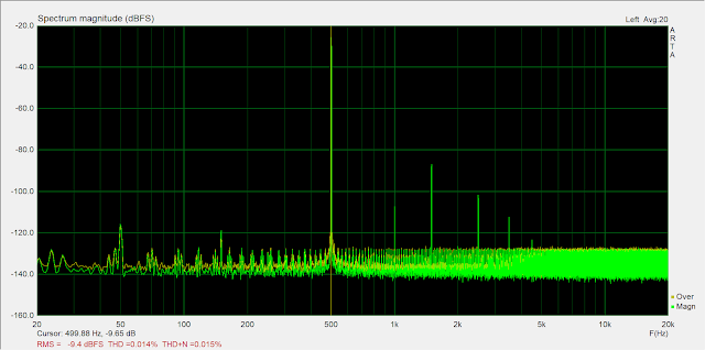
Next we can use this as a reference and measure the same parameters of the DI1000. As we can see from the below image our THD has gone up a bit. Whilst this may seem like a huge increase I'd say you would hardly notice it, if at all, during use especially when using affected guitar like I do.
When taking the measurement of my Interface's distortion I carefully set the dials for minimal THD, so what happens if I do the same for the DI1000? Now we see the best it can do. The datasheet states THD + N @ 1 kHz / 0 dBu < 0,005 %. I managed to get 0.0068% using a 500Hz sine wave, I also wasn't at 0dBu as that would start clipping my interface, so I do believe that the datasheet is accurate with it's statement.
A Small Update
I've been informed by my friend, Dylan, that where these DIs really suffer is in their low-frequency performance. As seen earlier the bass response wasn't as flat as the rest, but what happens to the THD down in that area? Here I used a 40Hz sine wave instead of the 500Hz one and we can see the THD has increased almost tenfold!
While I don't believe the above THD increase will be too audible, we can also see what happens when the interface begins to clip. Here I am using the same 40Hz sine wave but now I'm outputting at 1.7Vrms which is causing the DI to clip and drastically increasing the THD. This is very audible and doesn't sound good (or "musical")
Conclusion
I'll keep this section brief, I don't want to rehash what others have likely said. Overall I think this is a great bit of kit, especially for the £25 it set me back.
It has a ground lift which is the main reason I bought it. But the specs in terms of FR and THD are impressive to me also, I was expecting far worse than what I got. The build quality is good, the case is 3mm aluminium with nice thick rubber feet. Another nice feature is the ability to attenuate the signal, you'd not want to do this for noise reasons unless you have to but there's 40dB of attenuation in two 20dB steps available for hot signals.
There's also the ability to power it via a battery if phantom power isn't available, probably not something I'd ever use but nice to have.
One thing I do wish it has was some kind of clipping indicator, I've recorded guitar through this and while my interface wasn't showing any clipping there was some extra crackle/distortion, turning my effects volume down or hitting an attenuation button stopped this, therefore my DI must have been clipping. It would be nice to have an LED to indicate this like my interface has instead of relying on my ears working.


Comments
Post a Comment